Network Theorems
Superposition theorem:
Superposition theorem states that in any linear, active, bilateral network having more than one source, the response across any element is the sum of the responses obtained from each source considered separately and all other sources are replaced by their internal resistance.The superposition theorem is used to solve the network where two or more sources are present and connected.
Steps for Solving network by Superposition Theorem
Considering the circuit diagram A, let us see the various steps to solve the superposition theorem
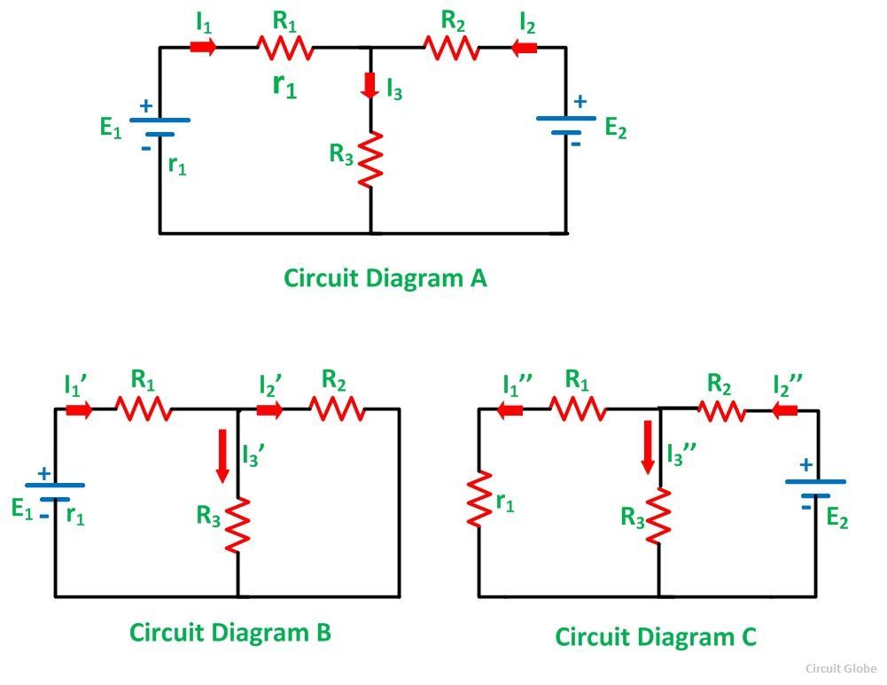 Step 1 – Take only one independent source of voltage or current and deactivate the other source.
Step 2 – In the circuit diagram B shown above, consider the source E1 and replace the other source E2 by its internal resistance. If its internal resistance is not given, then it is taken as zero and the source is short circuited.
Step 3 – If there is a voltage source than short circuit it and if there is a current source than just open circuit it.
Step 4 – Thus, by activating one source and deactivating the other source find the current in each branch of the network. Taking above example find the current I1’, I2’and I3’.
Step 5 – Now consider the other source E2 and replace the source E1 by its internal resistance r1 as shown in the circuit diagram C.
Step 6 – Determine the current in various sections, I1’’, I2’’ and I3’’.
Step 7 – Now to determine the net branch current utilizing the superposition theorem, add the currents obtained from each individual source for each branch.
Step 8 – If the current obtained by each branch is in the same direction than add them and if it is in the opposite direction, subtract them to obtain the net current in each branch.
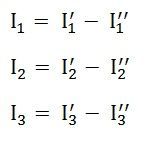
The actual flow of current in the circuit C will be given by the equations shown below
Example
Solution
Here 3.3K and 2K are in parallel, therefore resultant resistance will be
1.245K.
Here 3.3K and 4.7K are in parallel, therefore resultant resistance will be
1.938K.
Using
the superposition theorem, determine the voltage drop and current across the
resistor 3.3K as shown in the figure below.
Step
1: Remove the 8V power supply from the original circuit, such that
the new circuit becomes as the following and then measure the voltage across a
resistor.
Using
voltage divider rule voltage across 1.245K will be
V1=
[1.245/(1.245+4.7)]*5 = 1.047V
Step
2: Remove the 5V power supply from the original circuit such
that the new circuit becomes as the following and then measure the voltage
across a resistor.
Using
voltage divider rule voltage across 1.938K will be
V2=
[1.938/(1.938+2)]*8 = 3.9377V.
Therefore
voltage drop across a 3.3K resistor is V1+V2 = 1.047+3.9377=4.9847
Applications & Limitations of Superposition Theorem
The
superposition theorem cannot be useful for power calculations but this theorem
works on the principle of linearity. As the power equation is not linear. As a
result, the power used by the factor in a circuit with this theorem is not
achievable.
If
the load selection is changeable, then it is necessary to achieve each supply
donation and their calculation for each transform in load resistance. So this
is a very difficult method to analyze compound circuits.
The application of superposition theorem is,
we can employ only for linear circuits as well as the circuit which has more
supplies.
This theorem cannot be used for
non-linear circuits, but applicable for linear circuits. The circuit can be
examined with the single power source at a time, the Equivalent section
currents and voltages algebraically included discovering what they will perform
with every power supplies in effect. To cancel out all except one power supply
for study, substitute any power source with a cable; restore any current supply
with the break.
Norton's Theorem :
Norton’s Theorem states that – A linear active network consisting of independent or dependent voltage source and current sources and the various circuit elements can be substituted by an equivalent circuit consisting of a current source in parallel with a resistance.The current source being the short-circuited current across the load terminal and the resistance being the internal resistance of the source network.
Steps for solving a network utilizing Norton's Theorem:
Step 1 -- Remove the load resistance of the circuit.
Step 2 – Find the internal resistance Rint of the source network by deactivating the constant sources.
Step 2 – Find the internal resistance Rint of the source network by deactivating the constant sources.
Step 3 – Now short the load terminals and find the short circuit current ISC flowing through the shorted load terminals using conventional network analysis methods.
Step 4 – Norton’s equivalent circuit is drawn by keeping the internal resistance Rint in parallel with the short circuit current ISC.
Step 5 – Reconnect the load resistance RL of the circuit across the load terminals and find the current through it known as load current IL.
Example
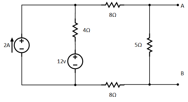
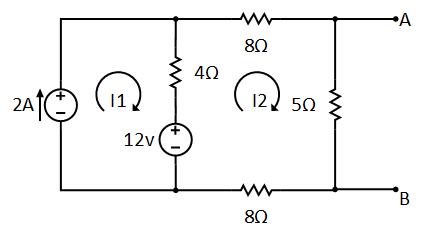
Suppose
we want to connect some variable resistor at terminal A-B and find Norton
equivalent circuit to the following example for the terminals.
The current I2 is flowing through 5Ω, so the voltage across the resistor will be:
find norton's current
Now we have both resistance RN and voltage Vth, so we can find out the Norton current IN as follow:
Norton's theorem limitation:
Norton's theorem is valid only for linear elements..
Norton's theorem is not valid for non-linear elements.
Norton's theorem is not applicable to the circuits consists of
unilateral elements or non-linear elements.
Thevenin’s Theorem
Thevenin’s Theorem states that – any complicated network across its load terminals can be substituted by a voltage source with one resistance in series. This theorem helps in the study of the variation of current in a particular branch when the resistance of the branch is varied while the remaining network remains the same for example designing of electronics circuits. A more general statement of Thevenin’s Theorem is that any linear active network consisting of independent or dependent voltage and current source and the network elements can be replaced by an equivalent circuit having a voltage source in series with a resistance, that voltage source being the open circuited voltage across the open circuited load terminals and the resistance being the internal resistance of the source.Steps for solving Thevenin's theorem.
Step 1 – First
of all remove the load resistance rL of
the given circuit.
Step 2 – Replace all the impedance source by their internal
resistance.
Step 3 – If sources are ideal then short circuit
the voltage source and open the current source.
Step 4 – Now find the equivalent resistance at the
load terminals know as Thevenin’s Resistance (RTH).
Step 5 – Draw the Thevenin’s equivalent circuit by
connecting the load resistance and after that determine the desired response.

Find the Equivalent Resistance (Rs)
Find the Equivalent Voltage (Vs)


For example, consider the circuit from the previous tutorials.

Find the Equivalent Resistance (Rs)
Find the Equivalent Voltage (Vs)
Firstly, to analyse the circuit we have to remove the centre 40Ω load resistor connected across the terminals A-B, and remove any internal resistance associated with the voltage source(s). This is done by shorting out all the voltage sources connected to the circuit, that is v = 0, or open circuit any connected current sources making i = 0. The reason for this is that we want to have an ideal voltage source or an ideal current source for the circuit analysis.
The value of the equivalent resistance, Rs is found by calculating the total resistance looking back from the terminals A and B with all the voltage sources shorted. We then get the following circuit.

The voltage Vs is defined as the total voltage across the terminals A and B when there is an open circuit between them. That is without the load resistor RL connected.

We now need to reconnect the two voltages back into the circuit, and as VS = VAB the current flowing around the loop is calculated as:

This current of 0.33 amperes (330mA) is common to both resistors so the voltage drop across the 20Ω resistor or the 10Ω resistor can be calculated as:
VAB = 20 – (20Ω x 0.33amps) = 13.33 volts.
or
VAB = 10 + (10Ω x 0.33amps) = 13.33 volts, the same.
Then the Thevenin’s Equivalent circuit would consist or a series resistance of 6.67Ω and a voltage source of 13.33v. With the 40Ω resistor connected back into the circuit we get:

and from this the current flowing around the circuit is given as:
which again, is the same value of 0.286 amps, we found using Kirchhoff’s circuit law in the previous circuit analysis tutorial.
Limitations for network n1:

(1) network
n1 should be linear and bilateral that means elements like diode and transistor
should not connected .
(2) network
n1 can have dependent or independent voltage or current source
(3) network
n1 may have initial condition
(4) network
n1 should not be mutually coupled with the network n2 that means magnetic
coupling should not present between network n1 and network n2
Limitation for network n2:
(1) network
n2 may be linear , non linear , time variant ,time invariant
(2) network
n2 may have dependent or independent voltage and current source
Uses of thevnin theorem :
(1) the one
of the main use of thevenins theorem is the replacement of a large part of a
network , often a complicated and uninteresting part , by a very simple
equivaent network .
(2) this
theorem helps in calculation of impedance(zth) in case of maximum power
transfer to load condition in a network .
Maximum Power Transfer Theorem
Maximum power transfer theorem states that the DC voltage source will deliver maximum power to the variable load resistor only when the load resistance is equal to the source resistance.
Similarly, Maximum power transfer theorem states that the AC voltage source will deliver maximum power to the variable complex load only when the load impedance is equal to the complex conjugate of source impedance.
Steps for Maximum power transfer theorem.
Find the maximum power that can be delivered to the load resistor RL of the circuit shown in the following figure.
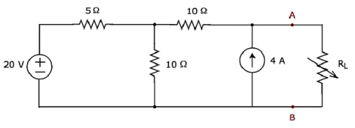
Step 1 − In Thevenin’s Theorem chapter, we calculated the Thevenin’s equivalent circuit to the left side of terminals A & B. We can use this circuit now. It is shown in the following figure.
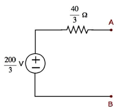
Here,Thevenin’s voltage
and Thevenin’s resistance
Step 2 − Replace the part of the circuit, which is left side of terminals A & B of the given circuit with the above Thevenin’s equivalent circuit. The resultant circuit diagram is shown in the following figure.
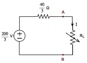
Step 3 − We can find the maximum power that will be delivered to the load resistor, RL by using the following formula.
Substitute and in the above formula.
Therefore, the maximum power that will be delivered to the load resistor RL of the given circuit is W.
Limitations:
One of the limitation of maximum power theorem is the efficiency is only 50% and therefore it can't be used in power systems where efficiency is the main concern.


